Aerodynamics
October 29, 2024
Matt Hammond
Dynamic Rollover
Definition: Susceptibility of a helicopter to a lateral rolling tendency.
Dynamic/Critical Angle: Angle, which, if exceeded, recovery is impossible. Angle varies based upon rate of roll and/or contributing factors. May occur during takeoff and landing to level or slopping ground
Contributing Causes
Physical Factors:
- Main rotor thrust
- Extreme CG (loading)
- Tail rotor thrust (translating tendency)
- Crosswinds
- Ground surface
- Slope Angle
Human Factors:
- Failure to take timely action
- Loss of visual reference
- Inattention
- Inexperience
- Inappropriate control inputs
3 Types of Rollover:
- Rollover on level ground (i.e. stuck skid)
- Rollover downslope (not enough cyclic on a steep slope)
- Rollover upslope (too much cyclic into slope when picking up)
Factors Influencing:
- Right skid down
- Left pedal inputs
- Lateral loading
- Crosswind
- High Roll Rates
Corrective Action:
- Smooth and moderate collective inputs are most effective in preventing dynamic rollover
- A smooth and moderate collective reduction is required at the onset of dynamic rollover
- Do not allow roll rates to build
- Concentrate of flying
Other:
- If dynamic rollover occurs, cyclic will have NO effect
- If on the verge of getting dynamic rollover, do NOT increase collective - decrease collective
- To help avoid dynamic rollover - FLY THE AIRCRAFT - if landing, until the full weight is on the landing gear. Or, if taking off, before any collective is applied.
- To get into dynamic rollover, there must be:
- Pivot Point (skid)
- Rolling Motion
- Exceeding of the critical rollover angle
Settling With Power
Definition: Condition of powered flight in which the helicopter settles in its own downwash. Also known as Vortex Ring State.
Cause
Normal Hover-induced airflow coming down through the rotor system.
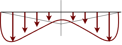
Normal Descent-opposing airflow is starting to hamper rotor’s induced flow.
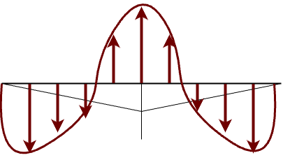
Vortex Ring State-the opposing airflow has cancelled the induced airflow = less lift.
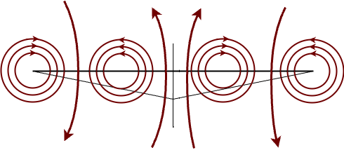
Conditions Conductive to Settling with Power (VSI)
- Vertical airspeed greater than 300 fpm
- Slow to no airspeed (less than ETL)
- Insufficient power to recover - high power (20 to 100 percent being applied)
Recovery
- If power is available, increase collective normally.
- If insufficient power:
- Increase airspeed
- Reducing collective (if altitude permits)
Conditions Conducive to Settle with Power
- Downwind approach
- Steep approach with high rate of descent (above 30 degrees)
- Formation landings with turbulence from other aircraft
- Hovering above max hover ceiling
- Hovering OGE
Retreating Blade Stall
Definition: A phenomenon resulting from the retreating blade not producing enough lift due to slow relative (the retreating blade not going as “fast” as the advancing blade) or burbling due to excessive angle of attack in compensating for dissymmetry of lift. As the speed of the retreating blade “decreases” as the forward aircraft speed increases, the retreating blade angle of attack must be increased to equalize lift throughout the rotor disk area. As the aircraft speed continues to increase, the retreating blade angle of attack is so great that the blade stalls (loses lift).
- The stall originates at the blade tip and moves inboard
- The critical angle of attack to stall the retreating blade is 15 to 20 degrees
Causes (STAALL)
- Steep turns (high G maneuvers)
- Turbulent Air
- Altitude - High DA
- Airspeed - High Airspeed
- Low Rotor RPM
- Loads - High Gross Weight
Signs
- Abnormal vibrations, then…
- Pitching up of the nose
- Left Roll
Corrective Action (RRRRI)
- Reduce Collective
- Reduce Airspeed
- Reduce the severity of the maneuver
- Reduce Altitude
- Increase Rotor RPM
Dissymmetry of Lift
Definition: Unequal lift between the advancing and retreating halves of the rotor disk caused by the different wind flow velocity across each half
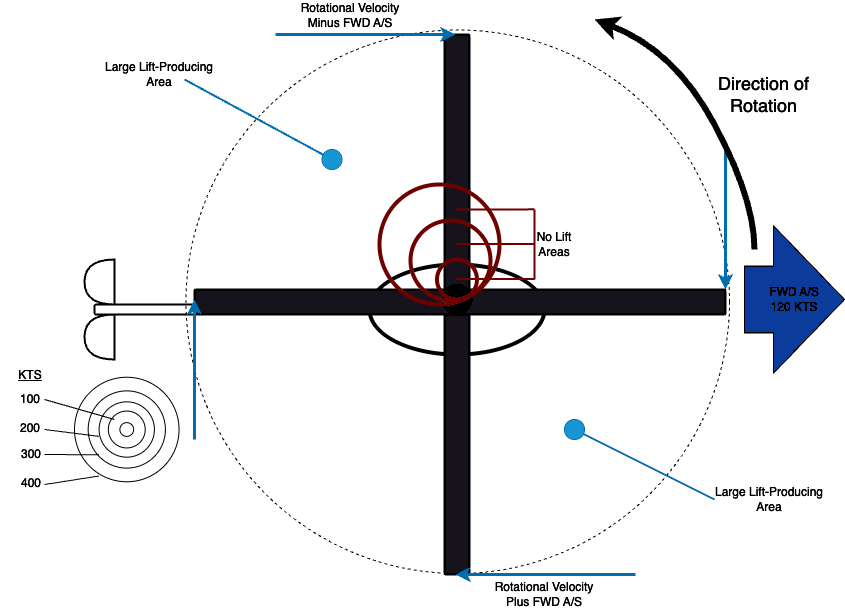
Causes
- Velocity of the advancing and retreating blades
- The advancing blade is going into the relative wind and has more speed
- The retreating blade is going with the relative wind and has less speed
- No Lift Areas
- The no lift areas are on the retreating blade side. Therefore, the advancing blade has more lift than the retreating blade
Translating Tendency
Definition: During hovering flight, the single-rotor helicopter tends to drift laterally to the right.
Cause
This tendency results from the thrust exerted to the right by the tail rotor (to compensate for the main rotor torque)
Compensated By
- The pilot by applying left cyclic during a hover
- A built-in left cyclic rigging
- Tilting the main transmission to the left
Transverse Flow Effect
Definition: The different airflow between the front half of the rotor system and the aft half
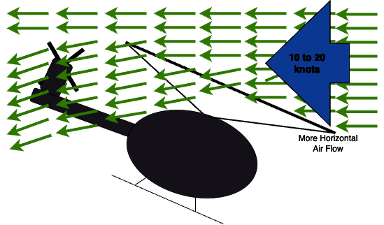
- Air moving across the rotor disk in forward flight is deflected downward because of the induced flow (downward velocity of airflow). The forward part of the rotor disk strikes the more horizontal airflow while the aft portion of the rotor disk receives the downward flow of air. This creates more drag and less lift in the aft portion of the rotor disk. This unbalance in the front and aft portion of the rotor disk creates a shaking of vibration effect. Since the aft portion has less lift and because of Phase Lag (an applied force happens 90 degrees later in the direction of rotation), the aircraft will roll right
- Pilot compensates by applying left cyclic
- Transverse flow effect most noticeable around ETL (10-20 kts)
Translational Lift
- Improved rotor efficiency resulting form directional flight
- Efficiency is improved with each knot of incoming wind
- As incoming wind enters, turbulence and vortices are left behind and air flow becomes more horizontal
- Increased efficiency continues until best climb speed is reached
Effective Translational Lift
- Rotor system completely outruns the recirculating of old vortices and begins to operate in undisturbed air
- 16-24 knots
- Nose pitch up and right rolling motion
- Because of dissymmetry of lift, gyroscopic precession and transverse flow effect
Airflow During a Hover
Blade Tip Vortex: Air swirl at the tip of the rotor blades. This vortex reduces the effectiveness of the outer blade portions.
| IGE Hover | OGE Hover |
|---|---|
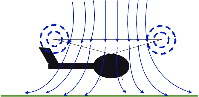 | 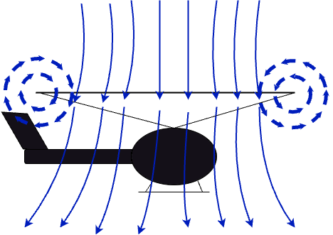 |
| Ground slows velocity of induced flow | With no ground, induced airflow has higher downward velocity |
| Ground interference reduces blade tip vortexes | Larger blade tip vortexes |
| Both of the above causes less power to hover | Both of the above causes more power to hover |
| IGE Hover | OGE Hover |
|---|---|
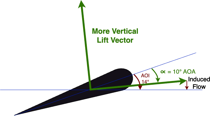 | 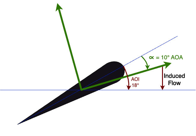 |
| Lift vector points more vertical | Induced flow is greater |
| Notice that the angle of attack stays the same for both IGE and OGE | Causes greater angle of incidence |
Airflow in Forward Flight
The velocity of the flow of air over the rotor system equal the speed of the helicopter. Because the blades of the helicopter turn in a circular pattern, the velocity of the airflow across a blade depends on:
- The position of the blade in the rotor disk at a given instant
- The airspeed of the helicopter
- The blade’s rotational velocity
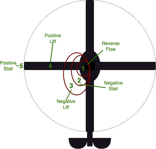
Blade Areas in Forward Flight:
- Reverse Flow: Air flow backward from the blade’s trailing edge to the leading edge. No lift.
- Negative Stall: Angle of attack exceeds the critical angle (15-20 degrees), producing a stall. Still no lift.
- Negative Lift: Angle of attack is below the critical angle (less than 15-20 degrees). But lift vector is pointing down, producing negative lift
- Positive Lift: Angle of attack is positive and producing positive lift
- Positive Stall: Angle of attack is positive, but too much - creating a stall region and no lift. Creates retreating blade stall.